Brief Project Overview
The purpose of this post is to try and document a proposal for a home automation implementation for different sensors and components using Arduino framework and hardware components that are easily available in the Arduino ecosystem.
The main driver was to steer away from having to install a WiFi chip on each and every sensor or component. The reasons for this are as follows:
- reduce or limit polluting the list of connected devices on your WiFi router.
- drastically reduce power consumption on sensors using alternative wireless chips, protocols and MCUs.
- reduce the overall cost of the sensor or device by using alternative wireless chips and MCUs.
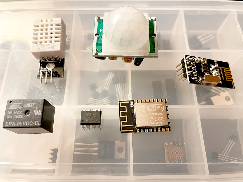
Software and hardware intended to be used:
- Arduino - probably the most popular electronics platform
- Atmel AVR MCUs - cheap and widely used microcontrollers.
- nRF24 - cheap and reliable wireless communication chip.
- ESP8266/ESP32 - WiFi chip that is cheap and popular amongst DIYs engineers.
- ESPHome - framework intended for ESP8266/ESP32 WiFi chips that uses simple configuration files to generate the firmware for your device.
- NRFLite - small footprint library for controlling nRF24 chips with only two pins.
High Level Diagram

The diagram should be self explanatory. ESPHome Hub is the central piece of the architecture. It is the bridge between the home automation console and the myriad of IoT devices that can be actuators, sensors or generic components. The architecture makes use of the already existing integration between ESPHome and Home Assistant, thus just building on top of this to connect custom IoT devices.
| Component | Description |
|---|---|
| Home Assistant | Open-source software for home automation that is designed to be the central control system for smart home devices with focus on local control and privacy. |
| ESPHome Hub | ESP8266/ESP32 based hardware device that has a custom implementation of the Smartpixy hub in order to connect and communicate with Smartpixy sensors and components |
| Sensors | Custom built Smartpixy sensors using Arduino and a protocol to communicate with ESPHome Hub |
| Components | Custom built Smartpixy components using Arduino and a protocol to communicate with ESPHome Hub |
ESPHome Hub Diagram

The hub as a central piece of the architecture will have two hardware modules that are used for wireless communication: the nRF24 chip for low power wireless communication and the actual ESP WiFi module to connect the hub to Home Assistant. The diagram also depicts a logical representation of the child devices as sensors and components. Whenever a new child device starts, it will send a heartbeat signal to the Hub. This will register the device in the devices list connected to the Hub.
Smartpixy Component Diagram

The component or sensor is really simple, compound out of a communication module nRF24, the actual MCU for processing the sensor data and the actual sensor or component that needs to be controlled.
Network Topology
A mesh of interconnected devices is usually the way to go for a professional network solution. The nRF24 chip already has a few libraries that offer the possibility to create a mesh of interconnected IoT devices, however this paper will present an alternative network topology that will focus to reduce the overall network complexity.
The objectives are:
- make use of a central hub or device to which all the other IoT devices will connect to and communicate with.
- have the possibility to support a large number of devices intermittently connected to the hub.
- support NRFLite library that has the possibility to connect nRF24 chip to a MCU with only two wires.
The nRF24 chip comes with quite a few interesting features that we can leverage to connect a large number of independent devices:
- Automatically packet handling - assemble, validate and disassemble the messages between sender and receiver.
- Auto acknowledgement - whenever a message is sent from one chip to another, for a short period of time the chips automatically switch roles such that the initial sender will receive an ACK packet back confirming that the receiver got the message.
- Acknowledgement payload - the ACK packet can contain an optional payload that can be sent pack to the sender as a response. We will make use of these feature to create a custom communication protocol.
- Auto retransmission - builds on top of the auto acknowledgement packet. Whenever the sender does not receive the ACK packet back, the chip will retransmit the message. With the growing number of IoT devices communicating with the same hub, the probability of message clashing will increase. To mitigate this the auto retransmission will be our ally.
- MultiCeiver - enables the chip to receive data on six different logical pipes, using the same frequency channel. In other words it opens the possibility to independently receive packets from six different devices at one time, preserving the above features for each pipe: auto packet handling, auto ACK, ACK payload and retransmission.
How Do the nRF24 Chips Communicate
For two chips to communicate, each chip must listen to an unique address that the other chip can use to send packets to. The ACK packet is handled a bit differently as described below.

Considering this simple scenario, nRF Sender will be configured having the transmission address set to 1 (TX: 1) and receiving address set to 1 as well (RX: 1). The nRF Receiver will listen on address 1 (RX: 1). nRF Sender will start emitting on address 1 a packet and immediately after that will switch to receive mode on address 1 to wait for the ACK packet from the nRF Receiver. As the nRF Receiver received the packet will use the same address 1 to send back the ACK packet.
The MultiCeiver receiver will have the possibility to listen to as many as 6 devices at one time. We will use this functionality to build the nRF Hub that will listen to multiple addresses (RX: 1, RX: 2 … Rx: n) and will be able to send back an ACK packet on each individual address or pipe.

When we need the nRF Hub to first initiate the communication, the situation described previously between two chips applies. The nRF Hub simply sets the TX address to one of the child nRF devices address and one of the pipes to listen to the same TX address for the ACK packet. Usually the pipe with the 0 index is used for receiving ACK packets from children, leaving out actually 5 addresses available to listen to other devices, not 6.
Smartpixy Communication Protocol
Considering our initial goal of having a large number of IoT devices communicating with the Hub and the fact that the nRF24 chip can only listen to 6 individual addresses at one time, we need to find an alternative communication protocol that can somehow satisfy our hypothesis. Knowing that the IoT devices will most of the time stay silent and rarely go back to the Hub to dump their data or receive updates from the Hub, then we are in a position of sharing the Hub communication pipes between multiple devices.
The protocol will be simple, we will use a similar approach used in programming where multiple threads need to secure access to one resource. In principle a device that would like to send data back to the hub will have to first acquire a time bound lock and then send the data. For this to work we will use two listening pipes on the hub:
- First pipe will be an open to all pipe. This pipe will wait for lock acquire requests from devices.
- Second pipe will be the exclusive communication pipe. This will be used by the child device to send data once the lock has been acquired.
For this to work we will have to ensure that the child devices do not misbehave, such that no child device will use the second pipe for communication if the lock has not been acquired yet, or flood the first pipe with too many lock acquire requests.
1. Sending data to the Hub
In order for a device to send data to the Smartpixy Hub, it will need to ask the Hub for a communication lock. To do this, we could use one pipe of the Hub to listen for these specific requests. This means that multiple devices will use the same pipe to send their request packet to the Hub. We will make use of the acknowledgement payload feature in order to send back to the child device the ACK packet containing the address of the exclusive pipe that they can use to privately talk to the Hub. With this approach there are a few issues. Let’s see what those issues are and how we can mitigate them:
- there is a good chance that the ACK packet will be received by all devices that sent the request for a communication lock. This is because all devices are listening on the same pipe for the ACK packet. However the hub will grant the lock only to one device and the device ID will be included in the ACK packet payload. This will inform the child devices of who got the communication lock.
- there is a good chance that packets might clash and nothing will get through to the Hub. This will be mitigated by the auto retransmission feature of the nRF24 protocol.
- the lock might already be assigned to a different device, the device requesting the lock will have to wait for 100ms before re-requesting the lock. 100ms is the timeout of the lock.
Here is a diagram of how the entire flow will look like. It starts with the lock request and then it follows with the actual data send.

Here is how the Hub will handle the lock request and the data receive. Please not that the ACK payload must be prepared before the device makes the request to the hub. The ACK payload is sent back automatically by the nRF24 chip upon receiving a packet from a device. We can only control the content of this ACK payload beforehand, that is why we are first buffering it.

2. Sending Data to Components
For the Hub to initiate the communication with other devices, it will have to temporary switch from receiving mode (RX) to transmitting mode (TX). While transmitting the Hub will be unable to receive any updates from the other devices, such that there is potentially a risk of data loss. To communicate with the other devices, the Hub will simply switch the TX address to point to one of the devices address and use the same address for the ACK packet sent back by the child devices. To limit or mitigate the chance of a data loss while the Hub is transmitting, we can increase the length of the auto retransmission interval of the child device, such that one of the auto retried packets will reach the Hub.
Communication Packet
As we would like to keep the size of the packet to a minimum, we are looking to binary serialise the data. The communication packet should be easy to serialise and deserialise. In order to properly deserialise the packet, the client must know upfront the content type of the packet. On top of this, because we may have packets that will end up to multiple clients, we will need to also specify the recipient of the packet, such that clients will drop packets that are not intended for themselves.
The structure of the packet could look like this:
| Field | Type | Description |
|---|---|---|
| commandType | enum | Identifies the structure of the payload expected |
| fromAddress | uint8_t | Identifies the sender device |
| toAddress | uint8_t | Identifies the recipient to whom the payload is intended to |
| payload | uint8_t[] | The binary payload of the packet |
Command Types
LOCK_REQUEST
Command initiated by the client to request a lock for exclusive communication with the hub.
Body - empty
Example
commandType: LOCK_REQUEST
fromAddress: 10
toAddress: 1
LOCK_DELIVER
Command initiated by the hub that informs the client of the lock request acquired by a specific client. The command will be sent back as an ACK payload. The device for which the lock is intended to is specified by the toAddress attribute.
Body - empty
Example
commandType: LOCK_DELIVER
fromAddress: 1
toAddress: 10
HEARTBEAT
Command initiated by the client to inform the hub of the liveness of the device and also send the device capabilities and settings.
Body
| Field | Type | Description |
|---|---|---|
| heartbeatInterval | uint32_t | Expected heartbeat interval in seconds. Hub will determine when the the connection has been lost if the heartbeat is missed for a number of times. |
| canReceive | bool | If the device also listens to commands from the Hub. |
Example
commandType: HEARTBEAT
fromAddress: 10
toAddress: 1
body:
    heartbeatInterval: 3600
    canReceive: false
DATAPOINT_REPORT
Command initiated by the client to report a specific metric recorded by the component or sensor.
Body
| Field | Type | Description |
|---|---|---|
| id | uint8_t | The index of the datapoint to be reported (eg: 1, 2, 3) |
| type | Enum | RAW - variable length BOOLEAN - 1 byte INTEGER - 4 byes STRING - variable length ENUM - 1 byte BITMASK - 4 bytes |
| length | uint8_t | The size of the raw data |
| valueBoolean | bool | boolean value if the datapoint type is BOOLEAN |
| valueInt | int | signed int value if the datapoint type is INTEGER |
| valueUnsignedInt | uint32_t | unsigned int value if the datapoint type is INTEGER |
| valueEnum | uint8_t | enum value if datapoint type is ENUM |
| valueBitmask | uint32_t | bitmask value if datapoint type is BITMASK |
| valueString | char[] | variable string value if datapoint type is STRING |
| valueRaw | uint8_t[] | binary data if datapoint type is RAW, the length is determined by the length attribute |
*bold attribute - are in an union, such that the size of the value held by the union would be determined by the largest member of the union, 4 bytes in this case. See the c++ union.
Example
commandType: DATAPOINT_REPORT
fromAddress: 10
toAddress: 1
payload:
    id: 1
    type: BOOLEAN
    length: 0
    valueBoolean: true
DATAPOINT_DELIVER
Command initiated by the hub to report back to the client a specific datapoint.
Body - the same data structured used for DATAPOINT_REPORT command.
Example
commandType: DATAPOINT_DELIVER
fromAddress: 1
toAddress: 10
payload:
    id: 1
    type: BOOLEAN
    length: 0
    valueBoolean: true
CONFIRM
Command initiated by the hub and used as an ACK payload to confirm that the packet received by the hub was expected to come from toAddress. This is going to be used by the client to asses that the command was indeed received and processed by the hub. If the toAddress is different from the one that the client has, the client should resort to replaying the packet.
Body - empty
Example
commandType: CONFIRM
fromAddress: 1
toAddress: 10
Programatic APIs
The programatic API should be simple, exposing only the bare minimum methods to complete the communication purposes. Coarse-grained perspective of the objects involved in the design might look like this:
- Device - object that represents the client device
- Hub - object that represent the hub
- HubDevice - objects that represents the client devices connected to the hub
Device APIs
- sendDatapoint(Datapoint &datapoint): void - send datapoint to hub, every communication details are hidden behind the implementation of this method.
- registerListener(uint8_t datapointId, const std::function<void(Datapoint)> &callback) - register callback for a specific datapoint ID when the device receives updates from the hub.
- tick(): void - processing method that handles the async operations and communication processes.
- getLastSendStatus(): SendStatus - get the last sendDatapoint communication status. This could could be model as an enum: PENDING, SENT, ERROR, etc
Hub APIs
- getDeviceList(): HubDevice[] - retrieves all the connected devices to the hub.
- registerListener(uint16_t deviceAddress, uint8_t datapointId, const std::function<void(Datapoint)> &callback) - register a listener for a specific device and datapoint ID to receive updates when a device sends the data updates to the hub.
- sendDatapoint(uint16_t deviceAddress, Datapoint *datapoint) - send datapoint to a specific device.
- getLastSendStatus(): SendStatus - get the sendDatapoint communication status. Similar to the device method this will return an enum about the last packet that has been sent.
- tick(): void - processing method that handles all the async processes.
Conclusion
Making use of the NRF24 wireless communication chip protocol we were able to create a custom protocol that can in theory accept thousands of devices to report back their data to a central hub.